Typical Installation Example
Last updated September 4, 2019 by Meitar M
Now that you understand that NYC Mesh is composed of end-user devices, indoor and outdoor routers, and a connection to the Internet, let’s put it all together by stepping through an example installation for a new NYC Mesh node at a very high level.
Bear in mind that while this page describes a typical installation, it is merely an example. In real life, an install may not follow these steps exactly, and there may be extra steps that must be taken to connect the new node which are not described here. For a more thorough treatment of this process, please refer to our New Node Installation Guide. Also, as a reminder, please read our FAQ instead of this page if you have not already done so and are simply curious about how NYC Mesh works at a very basic level.
When the installation is complete, we will have successfully connected a new apartment at a new location to the rest of the NYC Mesh network using an implementation that is similar to Figure 1, below:
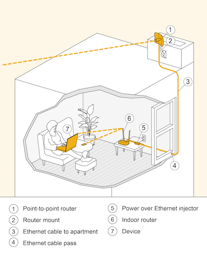
Figure 1: Typical single-apartment NYC Mesh node installation diagram.
Determining connection possibility
The process for installing a new node always starts with a join request by a prospective member of the community. This drops a pin for the location of the potential new node on the NYC Mesh node map, and starts a conversation between an Install Team leader and the prospective new member about what joining NYC Mesh means. One of the considerations discussed is how to physically connect to our network.
Since NYC Mesh is an “over the air” (OTA) network that connects new nodes “rooftop-to-rooftop,” the very first step is to make sure that the new node actually can be physically connected to the rest of the network. If the new node is simply too far away from an existing node, or if it cannot receive a good radio signal for other reasons such as obstacles that are in the way, we cannot proceed because we won’t be able to physically attach any equipment we install to the rest of our network.
However, let’s assume that the new node is somewhere in New York City that we actually can reach with the radio signal from one of our existing nodes. In this case, the Install Team leader will visit the potential new node location to perform a site survey. This simply means that they will check to make sure that the install team will be able to climb up on the roof safely and that the roof has at least some accomodations for installing routers and antennas. In certain cases where the new NYC Mesh member provides good panoramic photographs of the potential new node’s install location, the site survey can be skipped or expedited.
Assuming the site survey results in a green light for the install operation, the Install Team leader will coordinate with the new NYC Mesh member to schedule a time for the install. They will also recruit a node installation team made up of volunteers who have joined the NYC Mesh Installs Team, and they will be responsible for collecting the installation fee from the new member in order to cover the costs of the equipment that the install team will need to carry out their work.
Installing the outdoor router
After the install team arrives at the site of the new node location, politely introduces themselves to the new NYC Mesh member, and is directed to the rooftop, the first task to complete is to install the outdoor router. Although any of a variety of outdoor router hardware could be used, we’ll assume that the Install Team leader has brought along a Ubiquiti-branded LiteBeam AC, which is a very good device for this kind of installation. A picture of this device is shown in Figure 2, below.
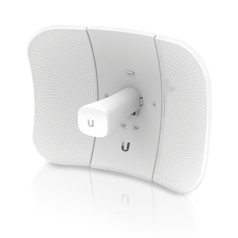
Figure 2: Ubiquiti LiteBeam AC, second generation. This router features a directional antenna and Power-over-Ethernet technology.
The Ubiquiti LiteBeam AC (or just “LiteBeam” for short) is a single piece of hardware that functions as both a router and an antenna in a single casing. Another major advantage of this device is that it receives electrical power over a standard Ethernet network cable using a technology called Power-over-Ethernet, or PoE for short. This means we can plug an Ethernet network cable into the LiteBeam and that same cable will serve as both a power cable and the network cable that will attach this outdoor router to the indoor router that we will install shortly.
Supplying power to the outdoor router
Once the Install Team has a good idea of the situation where the outdoor router will be installed, they will need to figure out how to run cabling from the new NYC Mesh member’s apartment or home to the roof. This cabling will supply electrical power to the LiteBeam as well as eventually supply network connectivity to the indoor router. The simplest way to accomplish this is to plug a Power-over-Ethernet (PoE) injector into a wall outlet near a window that will serve as a passage towards the roof.
With the PoE injector electrified, a properly crimped Ethernet cable can be run down from the roof, pushed through an access hole (called a cable pass) drilled into the window frame, and plugged into the PoE injector inside the apartment. The Ethernet cable is now also an electrical cable, and we can use it to supply power to the LiteBeam. Before the Install Team can begin to attach the LiteBeam to the roof, however, they need to find one or more existing NYC Mesh antennas installed on nearby rooftops.
Pointing the antenna towards other nodes
In order for the LiteBeam to provide the new NYC Mesh member with connectivity to the rest of the NYC Mesh network, it must be attached to the roof such that it points towards other NYC Mesh nodes. This is particularly important because the LiteBeam’s radio antenna is directional. In other words, it can only receive and send radio signals in a single direction, as opposed to “in all directions,” which is what an omni-directional antenna can do. If the Install Team mounts the LiteBeam to the roof without pointing it in the correct direction, the new node will not be connected to the rest of NYC Mesh and will, to put it bluntly, simply not work.
After plugging the Ethernet cable that was run into the apartment and plugged into the PoE injector into the Ethernet-plus-power port on the bottom of the LiteBeam, the Install Team can connect directly to the LiteBeam using their laptops or smartphones over its own, dedicated management network. This network is simply another 2.4Ghz Wi-Fi network that provides access to the administrative Web-based interface of the LiteBeam hardware itself.
Once logged into the LiteBeam’s admin interface, the Install Team members can use the built-in antenna alignment tool and companion app for Android or iOS, to find the best position in which to mount the LiteBeam to the roof. Radio signal strength is measured in units of decibel-milliwatts, or dBm, and we like to make sure our outdoor routers are showing between -65dBm to -45dBm on both receive (RX) and transmit (TX) readings for optimal performance. Figure 3 shows a screenshot of the Ubiquiti mobile app’s antenna alignment feature.

Figure 3: Ubiquiti UNMS antenna alignment mobile app.
Mounting the outdoor router
Once the Install Team determines the correct angle at which to point the antenna so that it can successfully receive and send radio signals to other NYC Mesh nodes, they must next physically attach the antenna to the roof so that it remains securely in place. Figure 4 shows a LiteBeam attached to a roof edge using a pipe mount.
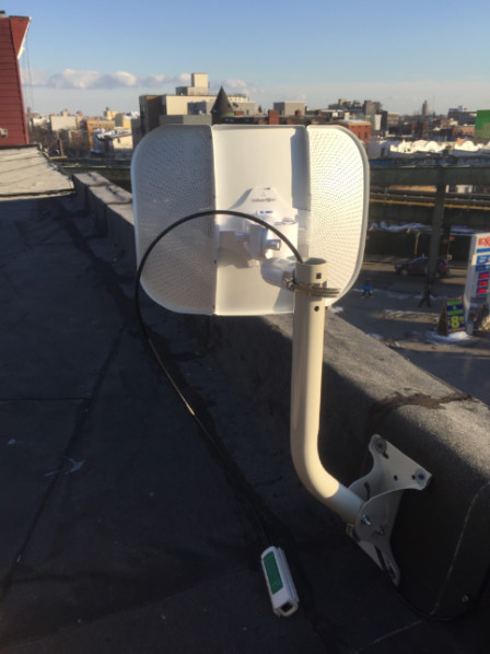
Figure 4: Ubiquiti LiteBeam AC mounted on a roof edge.
Depending on the roof’s construction, the Install Team may choose to mount the antenna on an old TV pole, a wall, a chimney, or any existing infrastructure. With the building owner’s permission, they may also make modifications such as adding a new pole on which to mount the NYC Mesh antenna. Figures 5, 6, 7, and 8 show these additional mounting techniques.
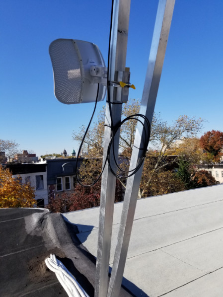
Figure 5: Ubiquiti LiteBeam AC mounted on existing roof infrastructure.
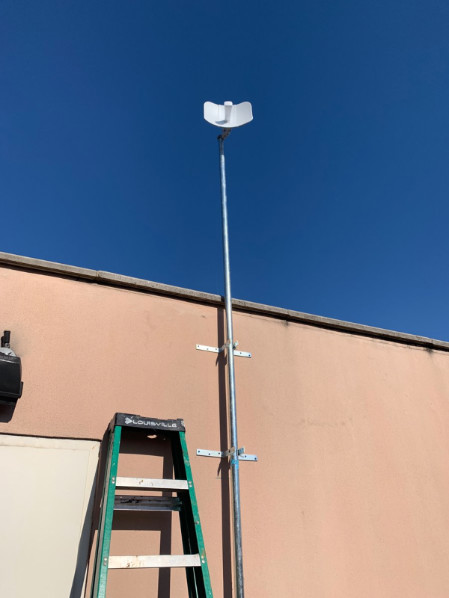
Figure 6: Ubiquiti LiteBeam AC mounted on a tall roof pole.
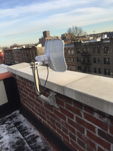
Figure 7: Ubiquiti LiteBeam AC mounted to a brick wall on a building roof.
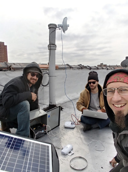
Figure 8: Ubiquiti LiteBeam AC mounted to a large roof pipe.
Attaching the outdoor router to NYC Mesh
The final step to perform on the roof is to attach the LiteBeam to the NYC Mesh network by configuring its network settings appropriately. The Install Team leader will have prepared a LiteBeam configuration, upload it into the LiteBeam via the administrative interface, and save the new configuration. If successful, this should supply the LiteBeam with an NYC Mesh internal IP address and prepare it for use by the indoor router, which will be installed next.
Installing the indoor router
With the outdoor router successfully aligned, mounted, and configured, the next step is to connect it to the indoor router so that end-user devices can be connected, too. Since the Install Team already has an Ethernet networking cable running from the roof to the apartment, this part of the install process is especially easy. All that’s required is to provide the new NYC Mesh member with an indoor router, such as the TP-Link model TL-WR841N 300Mbps Wireless N Router, plug it into an electrical outlet, and plug the Ethernet cable into the indoor router’s wide-area network (WAN) or upstream port.
These TP-Link routers are ordinary consumer home routers, so they ship from the factory with the Dynamic Host Configuration Protocol (DHCP) installed and activated, which makes setup a snap, but see our detailed configuration instructions for more information. If the new NYC Mesh member prefers, they can also supply their own indoor router. They can also elect to configure it with a custom wireless network name (known as a Service Set Identifier or SSID in networking lingo) and a password to protect their home network from unauthorized access.
Verifying the install
Once the outdoor router and the indoor router are both installed successfully, the new node should be operational. This means the NYC Mesh member should be able to access both intra-mesh services as well as connect to any available Web site on the open Internet through their new NYC Mesh connection. Try browsing the Internet as you normally would to make sure everything works as expected. If so, congratulations, you are now connected to NYC Mesh!
Alternative installation examples
The above example is of a single-apartment installation connected via point-to-point radio link using an Ubiquiti LiteBeam AC directional outdoor router, which is a typical configuration for new nodes. However, many other configurations exist throughout NYC Mesh. These include multi-apartment installations with point-to-point upstream links, single-apartment installs with omni-directional upstream links, and a combination of directional and omni-directional installations. The specifics of a given node installation is determined as a collaboration between the new NYC Mesh node owner, the Install Team leader, and the rest of the NYC Mesh volunteer community.
Some node locations are ideally suited to provide neighboring residents access to NYC Mesh, either due to the characteristics of their building or simply their geographical location. For instance, especially tall buildings provide ample opportunity to extend the range of the network simply due to the fact that their height lets us reach over obstacles. In these cases, the Install Team may opt to deploy an omni-directional antenna in combination with a point-to-point directional antenna in order to strategize for the future expansion of the mesh in the new node’s neighborhood.
Such a configuration may require additional up-front planning in order to accomodate longer cables, cable passes into more than one apartment, multiple antenna alignments and mounts, and more. For example, Figure 9 shows a variation on the simple configuration described above in which multiple apartments in the same building are connected to NYC Mesh and two outdoor routers are installed instead of one in order to increase the density of the mesh in the neighborhood.
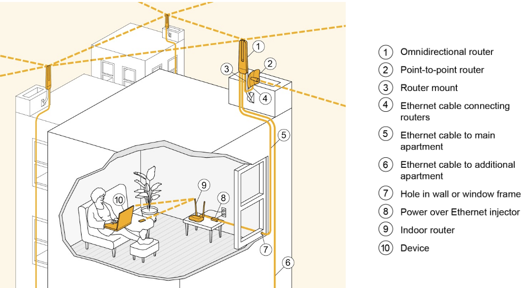
Figure 9: Example multi-router installation with omni-directional and directional (point-to-point) upstream links offering NYC Mesh connectivity to multiple apartments in the same building.
Figures 10, 11, and 12 show photographs of the rooftop installation diagramed in Figure 9 in which the new node has both an omni-directional router (specifically, a MicroTik OmniTik 5 PoE AC) and a directional router (a Ubiquiti LiteBeam AC) installed.
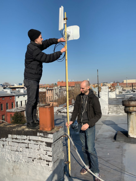
Figure 10: Photograph of a rooftop bearing both an omni-directional and a directional router antenna.
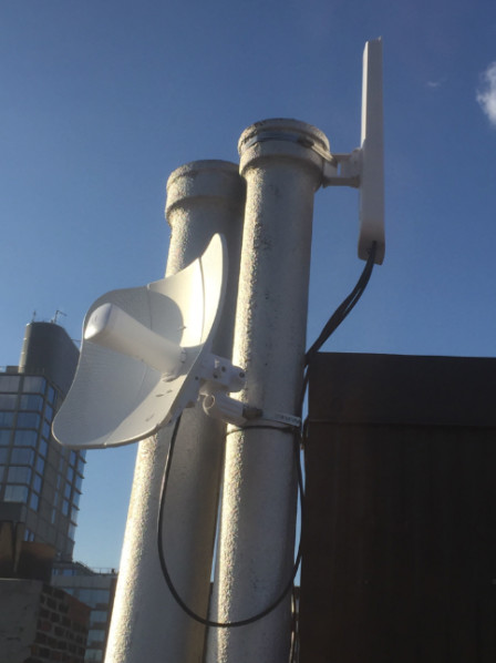
Figure 11: Photograph of a rooftop bearing both an omni-directional and a directional router antenna.
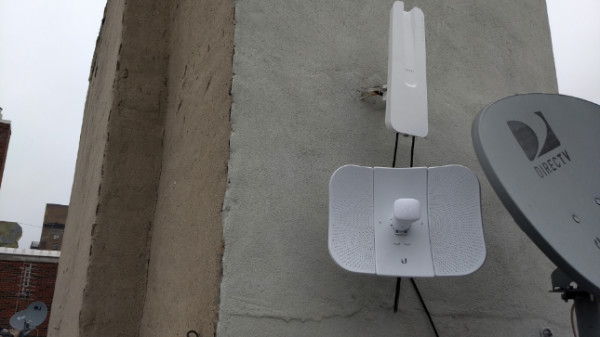
Figure 12: Photograph of a rooftop bearing both an omni-directional and a directional router antenna.
This sort of installation is especially nice on shared rooftops as the MicroTik OmniTik device can also provide direct end-user connectivity via Wi-Fi on your roof and allow an additional four apartments in the building to connect over wired Ethernet. Meanwhile, the OmniTik also provides omni-directional radio extension of the mesh for another two to three New York City blocks, which is a major boon to the neighborhood. If another MicroTik OmniTik outdoor router is installed within this two or three block radius, they will mesh with each other, thus improving reliability and access to the Internet for the neighboring community while also providing a further opportunity to continue expanding the mesh.
Figure 13 shows a MicroTik OmniTik omni-directional router alone on a rooftop.
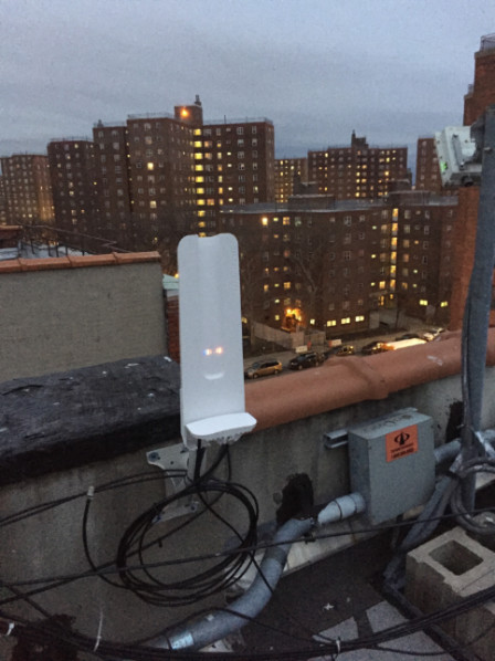
Figure 13: MicroTik OmniTik 5 PoE AC on a rooftop either alone or not positioned near a second outdoor router.
Hub node installation examples
A particularly good rooftop location can be “beefed up” to allow for more connectivity over time. Good rooftops are those that are high enough, in a particularly densely populated part of a neighborhood, and so forth. When we gain access to such a prized spot, we may install additional outdoor routers to provide extra coverage to the area using what we call sector antennas. These are typically stronger 120° directional antennas, such as the Ubiquiti LiteAP Sector device. These are often used to connect hub nodes together.
Figures 14, 15, 16, and 17 show examples of these “beefed up” node installations:
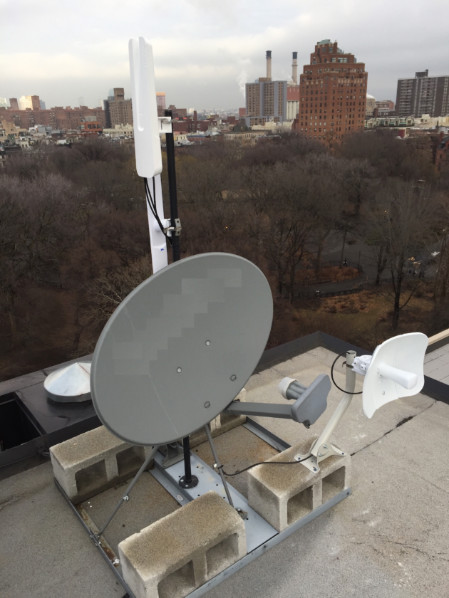
Figure 14: Hub 100 is shown here with three separate antennas installed in close proximity.
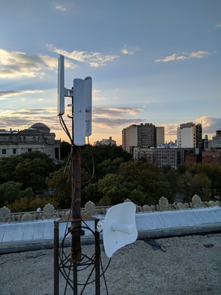
Figure 15: So-called ‘supernode 4’ has a LiteBeam directional router and three LiteAP Sector antennas.
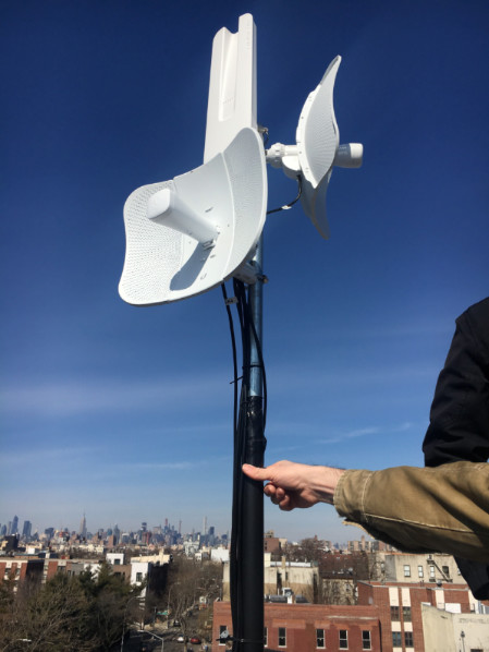
Figure 16: Hub node 1350 has two LiteBeams and an OmniTik installed.
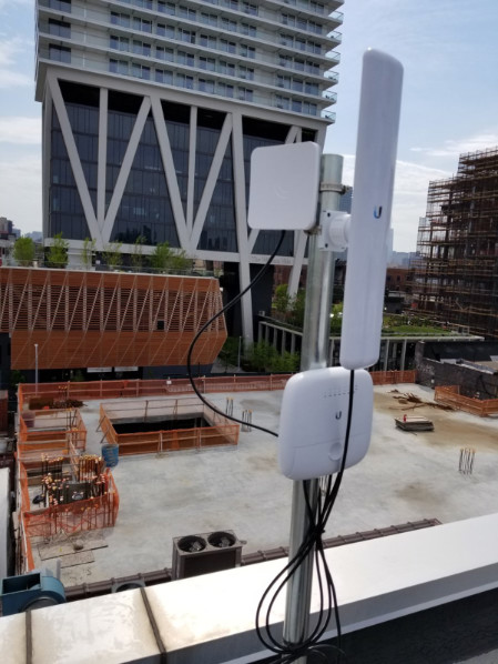
Figure 17: The Greenpoint hub has numerous omni-directional and directional antennas installed.